The vcad kernel is a purpose-built BRep (boundary representation) modeling kernel written in Rust — roughly 285K lines across 70+ focused crates, each owning one capability. This page catalogs every feature area, with examples authored in loon and rendered by the kernel's own pipeline: loon source → IR → BRep evaluation → tessellation → vcad-render. Every image below is the kernel's actual output.
Modeling Core
Analytic Primitives
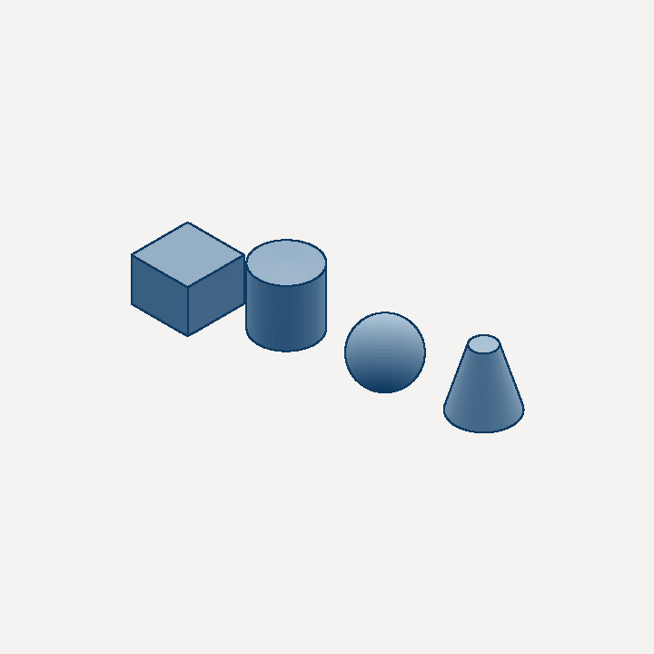
vcad-kernel-primitives constructs boxes, cylinders, spheres, and cones as exact BRep solids — a cylinder is a real CylinderSurface with analytic caps, not a polygon approximation. Downstream operations (booleans, fillets, ray tracing) work against the true surface.
[let box [translate -70 0 0 [cube 40 40 30]]]
[let cyl [cylinder 20 40]]
[let sph [translate 70 0 20 [sphere 20]]]
[let cn  [translate 120 -20 0 [cone 20 8 40]]]
[root [union box [union cyl [union sph cn]]] "aluminum"]
Half-Edge Topology
vcad-kernel-topo stores vertices, edges, loops, faces, shells, and solids in slotmap arenas with O(1) stable handles. Euler operators and non-allocating adjacency iterators make topology surgery — face splitting, edge merging, shell repair — fast and safe. See BRep Kernel for the full data-structure walkthrough.
Surfaces and Curves
vcad-kernel-geom implements the Surface trait for planes, cylinders, cones, spheres, tori, and bilinear patches, plus 3D/2D curve types for edges and trim loops. vcad-kernel-nurbs extends this with full B-spline curves and surfaces (knot vectors, weights, control grids) for freeform geometry.
Exact Predicates
vcad-kernel-math provides linear algebra, transforms, and Shewchuk's adaptive-precision predicates (orient2d, orient3d, incircle, insphere) via the robust crate. Geometric decisions — is this point above that plane? — are exact, not floating-point guesses, which is what keeps booleans from producing holes and inverted faces on near-degenerate input.
Persistent Topological Naming
vcad-kernel-naming gives faces stable names derived from their generating operations (n3:top, n1:side, with deterministic split ordinals through booleans) instead of ephemeral arena keys, and names edges by their adjacent-face pair. Downstream references — EdgeQuery::Named on an edge blend — re-resolve after an upstream parameter change, so a fillet stays on the intended edge when the parent box is resized. Resolution is fail-closed: an ambiguous or lost reference is an explicit error (with a geometric-hint fallback matcher), never a silent rebind to the nearest edge.
Operations
Boolean Operations
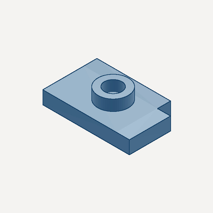
vcad-kernel-booleans implements union, difference, and intersection through a four-stage pipeline: AABB broadphase filtering, analytic surface-surface intersection (with a sampled fallback), exact-predicate face classification via ray casting and winding numbers, and a sewing stage that trims, splits, and merges faces with topology repair. The part below is one union and two differences:
[let plate  [cube 80 50 12]]
[let boss   [translate 40 25 12 [cylinder 14 10]]]
[let bore   [translate 40 25 -1 [cylinder 8 25]]]
[let corner [translate 68 -4 -1 [cube 16 16 14]]]
[root [difference corner [difference bore [union boss plate]]] "steel"]
Every result is held to a post-boolean validity oracle: probe points are classified against both operands, the operation's set semantics predict which probes must land inside the result, and a result that disagrees (or has inverted orientation) is rerouted to a mesh-CSG fallback — plane-split fragments classified by exact-predicate ray parity — instead of being returned as a plausible-looking wrong solid. Arrangements the analytic splitters cannot yet represent (intersecting circle arrangements on a sphere, sphere×cylinder crossings, unequal perpendicular cylinders) take the same fallback, trading semantic surfaces for a correct-volume triangle-soup B-rep. If even the fallback fails validation, the boolean returns an error rather than wrong geometry.
Fillets and Chamfers
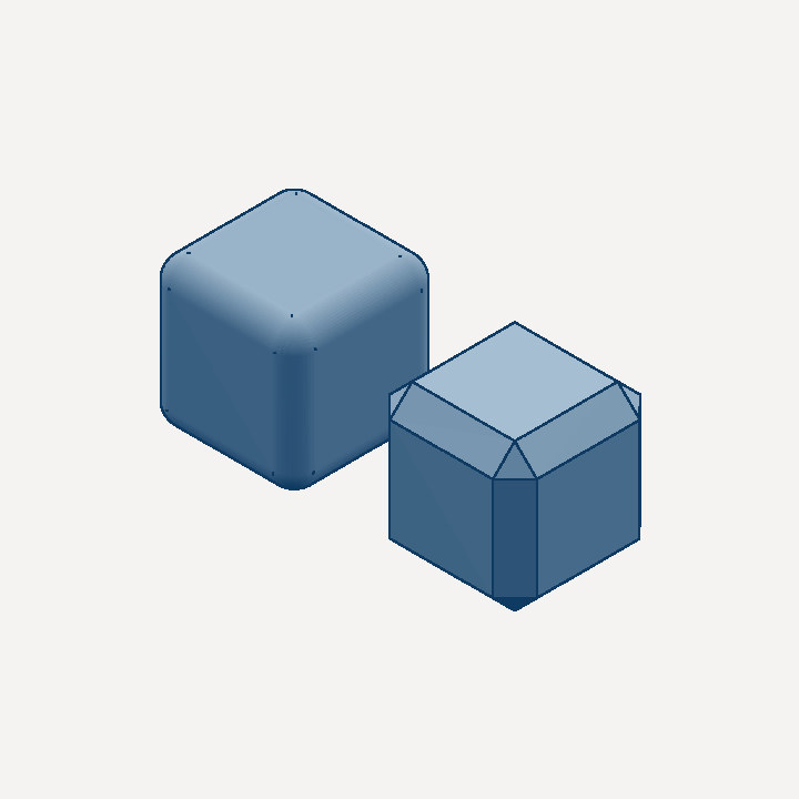
vcad-kernel-fillet rounds or bevels edges directly on the BRep — inserting true cylindrical and spherical blend faces rather than faceting the mesh. Left: [fillet 6 ...]; right: [chamfer 6 ...].
[let a [fillet 6 [cube 40 40 40]]]
[let b [translate -60 0 0 [chamfer 6 [cube 40 40 40]]]]
[root [union a b] "aluminum"]
Shell and Patterns
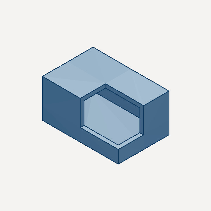
vcad-kernel-shell hollows a solid by offsetting its surfaces inward — each Surface knows how to offset itself analytically (a cylinder shrinks its radius, a plane translates). It also provides linear and circular patterns. Below, a box shelled to a 3 mm wall, with a cutaway to show the interior:
[let hollow  [shell 3 [cube 60 40 30]]]
[let cutaway [translate 30 20 10 [cube 40 30 30]]]
[root [difference cutaway hollow] "abs"]
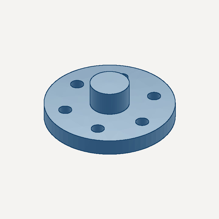
A circular pattern turns one hole into a bolt circle in a single operation:
[let disc  [cylinder 40 10]]
[let hub   [translate 0 0 10 [cylinder 12 15]]]
[let hole  [translate 28 0 -1 [cylinder 4 12]]]
[let holes [circular-pattern 0 0 0 0 0 1 6 360 hole]]
[root [difference holes [union hub disc]] "steel"]
Mirror and Symmetry
Mirror reflects a solid across an arbitrary plane — [mirror ox oy oz nx ny nz s] — but the overwhelmingly common case is a principal plane through the origin, so the stdlib provides [mirror-x s], [mirror-y s], and [mirror-z s], each negating exactly one coordinate. Never hand-mirror geometry by negating coordinates in a parametric function: the sign rules for extruded plates and rotated cylinders are subtle (a plate extruded along −Y needs its offset flipped and its thickness added back), and a mistake is silent.
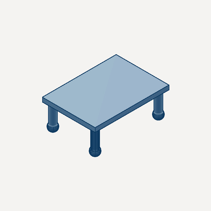
Symmetric patterns go one step further and union a solid with its own mirror image, so the two halves are one expression and cannot drift apart: [mirror-pattern nx ny nz s] (with [mirror-pattern-x s] / -y / -z sugar) for a left/right pair, and [quad-pattern s] for the 4-fold X-and-Y case that describes a quadruped's legs, a 4-post frame, and most vehicle chassis. One leg becomes four:
[let leg   [translate 60.0 40.0 0.0 [union [sphere 8.0] [cylinder 6.0 40.0]]]]
[let legs  [quad-pattern leg]]
[let deck  [translate -70.0 -50.0 40.0 [cube 140.0 100.0 8.0]]]
[root [union deck legs] "aluminum"]
The invariant worth asserting on any mirrored assembly: the centre of mass must lie on the mirror plane. crates/vcad-eval/tests/mirror_symmetry.rs checks exactly that, and it catches every mirroring sign error in one measurement.
Assemblies mirror too, and that is where the sign rules actually bite — a joint anchor has to flip together with its axis. Under a reflection M, conjugating a rotation gives M · R(a, θ) · M = R(−M a, θ), so a hinge keeps driving its mirrored child through the same state and the same limits only if its axis becomes −M a: the component along the mirror normal keeps its sign and the other two flip. Mirroring across X therefore leaves an X-axis hinge alone and negates a Y- or Z-axis hinge. A prismatic axis is a displacement rather than a pseudovector, so it transforms the other way, a' = M a.
[mirror-group-x "-r" side] (and -y / -z) encodes both rules. Author one side as an assembly and mirror it: parts are reflected geometrically, instances take the mirrored placement and point at the mirrored part, joint anchors mirror, axes follow the rules above, and a joint endpoint naming an instance outside the group — a shared body, the ground — keeps its name so both sides hang off the same parent. [assembly-join chassis mirrored] splices the result back into the machine.
[let one-side
  [assembly
    #[[part "femur" femur-solid "abs"]]
    #[[instance "leg" "femur" 25.0 12.0 0.0]]
    #[[revolute-joint "hip" 0.0 1.0 0.0 -90.0 90.0
        "body-i" 25.0 12.0 0.0 "leg" 0.0 0.0 0.0]]
    "body-i"]]
[assembly-join chassis [mirror-group-x "-r" one-side]]
crates/vcad-eval/tests/assembly_symmetry.rs drives both hips to the same state and asserts the whole assembly's centre of mass stays on the plane — with a deliberately chiral leg, so a copy that is translated but not reflected fails too.
Sketches and Constraints
vcad-kernel-sketch models 2D profiles (lines, arcs) on arbitrary planes, and vcad-kernel-constraints solves geometric constraints — coincident, horizontal/vertical, parallel, perpendicular, tangent, distance, length, radius, angle, equal-length, fixed — with a Levenberg-Marquardt solver using adaptive damping. Sketches feed every profile-based operation below.
Design Constraints (Document-Level)
vcad-design-constraints generalizes the sketch solver to the whole document: one constraint set spans PCB layout (footprint positions/rotations, board-outline vertices and edges), sketch geometry, and mechanical part edges addressed through the topological naming system. Dimensional constraints are expression-valued ("board_width - 2*edge_margin") over named document parameters, so changing a parameter re-solves the layout; driven: true makes a reference dimension that is measured and back-annotated instead of enforced. Cross-domain constraints treat part geometry as authoritative — a connector can be held coincident with an enclosure cutout edge, with fail-closed anchor resolution (an ambiguous or lost edge name skips the constraint with an error, never a silent rebind). Every constraint doubles as a constraint.* receipt claim, re-verified as Holds / Stale / Violated by verify_receipt. Exposed via the add_constraint / list_constraints / solve_constraints MCP tools and the board editor's Constrain tool.
Extrude, Revolve, Sweep, Loft
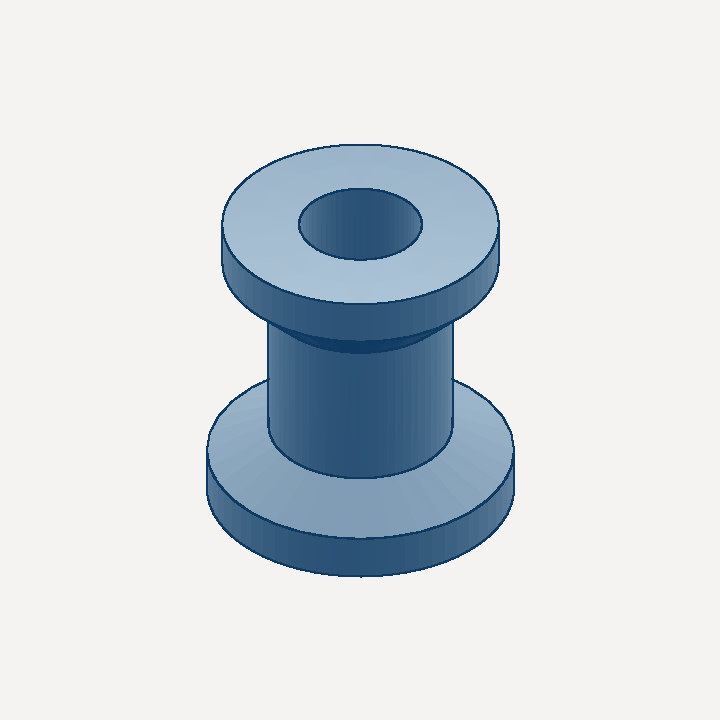
vcad-kernel-sweep turns closed sketch profiles into solids. Revolve spins a profile around an axis:
[let profile [sketch 0 0 0 1 0 0 0 0 1 #[
  [line 8 0 20 0] [line 20 0 20 6] [line 20 6 12 10]
  [line 12 10 12 30] [line 12 30 18 36] [line 18 36 18 42]
  [line 18 42 8 42] [line 8 42 8 0]
]]]
[root [revolve 0 0 0 0 0 1 360 profile] "brass"]
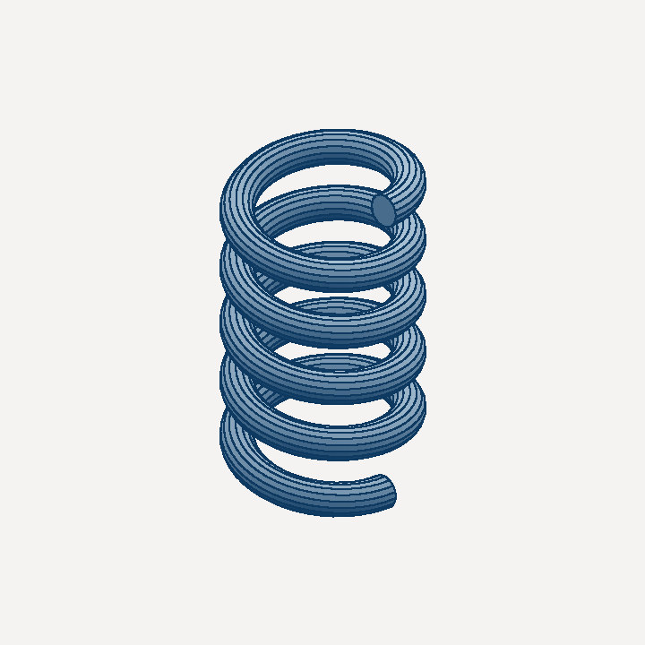
Helical sweep carries a circular profile along a helix — a compression spring in four lines:
[let profile [sketch 0 0 0 1 0 0 0 0 1 #[
  [arc 3 0 -3 0 0 0 true]
  [arc -3 0 3 0 0 0 true]
]]]
[root [sweep-helix 15 12 60 5 profile] "steel"]
A cam track, a bayonet slot, a J-slot or a lead-in ramp is dimensioned
differently — not as turns and a pitch, but as rise per degree of arc,
with named angles for the lead-in, the detent and the pocket. helix and
sweep say it that way:
[root [pipe [profile-rect 3.0 2.0]
            [sweep [helix 34.5 0.0667 0.0 15.0]]] "aluminum"]
That is a 3 mm x 2 mm channel section carried 15 deg around r34.5, rising
0.0667 mm per degree. The profile's x is the radial offset from the path
radius and its y is the axial offset; the cross-section is held in that
radial/axial plane rather than square to the tangent, which is what a radial
section of the finished part shows and what makes the swept floor land on
path z(theta) + min(profile y) exactly.
When the height is not a constant rate, add knots. cam-path takes a flat
#[deg z ...] list, so a rise-plateau-drop detent or a flat pocket is
expressed directly rather than approximated by stacked z-bands:
[root [pipe [profile-polyline #[-1.6 0.0  1.6 0.0  1.3 1.6  -1.3 1.6]]
            [sweep [cam-path 34.5 #[3.6 -0.25  9.6 0.15  10.3 0.25
                                    11.3 0.25  11.6 0.15  18.4 0.15]]]]
      "aluminum"]
Knots always land exactly on path samples, so a plateau's corners survive the
faceting. The step is 0.5 deg by default; helix-res and cam-path-res take
it explicitly. The swept solid is capped at both ends, so it is watertight
standing alone and can be subtracted through a wall.
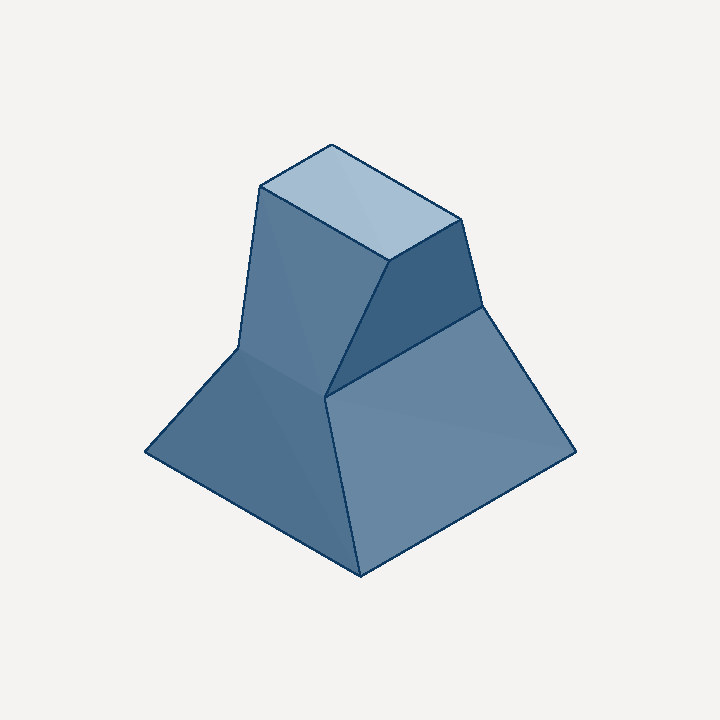
Loft interpolates a solid through a sequence of cross-sections:
[let base [sketch 0 0 0  1 0 0 0 1 0 #[ ... 60x60 square ... ]]]
[let mid  [sketch 0 0 30 1 0 0 0 1 0 #[ ... 24x44 rectangle ... ]]]
[let top  [sketch 0 0 60 1 0 0 0 1 0 #[ ... 36x20 rectangle ... ]]]
[root [loft #[base mid top]] "aluminum"]
Text and Sheet Metal
vcad-kernel-text converts text to sketch geometry for embossing and engraving. vcad-kernel-sheet models sheet-metal parts — flanges, bends — with lossless unfolding to a flat pattern.
Unfolding also runs in reverse, on geometry the sheet-metal ops did not author. vcad_kernel_sheet::flatten takes the triangle mesh of any solid — an extruded sketch, a boolean result, an imported STEP — recognises its constant-thickness walls and the cylindrical bends between them, and rebuilds the panel/bend graph, so a part modelled as an ordinary plate still yields a fab-ready DXF and a bend table. It is the mechanical counterpart of board_from_solid: solid in, manufacturable 2D out, no second representation to drift.
Recognition is a chain of geometric tests, each of which fails loudly rather than guessing:
- Triangles are grouped into edge-connected planar clusters.
- A panel is a pair of antiparallel, overlapping clusters; the smallest separation shared by every pair is the material thickness (which is why a 100×50×5 plate isn't read as a 50 mm-thick part standing on edge).
- Bends are the curved bands between non-parallel panels — found by walking triangles whose normals are perpendicular to the bend axis
nP × nC, which excludes the flat side wall of an L-bracket, whose normal lies along that axis. Each cylindrical surface's own area gives its radius:A = θ·R·W. - Finally the round-trip:
Σ panel_area·t + Σ bend_volumemust reproduce the solid's own volume. A part that isn't really constant-thickness sheet — a drafted or tapered wall — fails here instead of silently emitting a wrong outline.
Exposed to agents as the flat_pattern_from_solid MCP tool, which flattens a whole document at once and groups identical parts into one pattern × quantity (mirror-image parts stay separate — a chirality-sensitive profile signature keeps a left- and right-hand bracket from collapsing into "×2").
Fasteners
Fasteners are the most repeated primitive in a real assembly, so they are a form rather than a hand-built union of two cylinders. [bolt] takes a catalog designation, a head style, and the two points its axis runs between:
[let holes  [circular-pattern 0 0 0  0 0 1  6 360
              [clearance-hole "M4" 10  22 0 -1  0 0 1]]]
[let flange [difference holes [cylinder 30 8]]]
[root [union flange [bolt-circle "M4x12" "shcs" 44 6  0 0 8  0 0 -1  8]] "steel"]

Three things fall out of declaring the axis instead of composing rotations by hand:
- Orientation is derived. Head and shaft are one solid aligned to the from→to axis, so mirroring a subassembly mirrors the fastener with it — heads cannot end up on the far side of a flange with shafts pointing into free space.
- Heads are honest.
shcs(ISO 4762) andbhcs(ISO 7380) stand proud by their real height, andflat(ISO 10642) is genuinely countersunk — flush, zero protrusion. A protruding head is where the model says it is, so a clearance check against a swept volume means something. - Counts come from the geometry. Every placement emits a
{catalog_id, qty}line onto the document — multiplied through patterns, so a six-boltbolt-circlereports six — andbom_createseeds its COTS lines from that instead of from a hand tally.
The catalog behind search_mechanical_parts supplies stocked lengths, so M4x11 is rejected rather than modeled; [bolt-stacked] adds washers and nuts on the same axis and checks the length against the grip plus the stack, refusing a bolt that is too short to reach or too long for a blind hole. [clearance-hole] and [tapped-hole] take the same thread designation (ISO 273 medium fit, coarse-thread tap drill), so a hole and the fastener that goes in it cannot disagree.
Tessellation and Rendering
Tessellation
vcad-kernel-tessellate converts BReps to watertight triangle meshes with curvature-adaptive sampling and trim-loop-aware triangulation. This feeds the viewport, STL/GLB export, physics collision shapes, and the images on this page.
vcad-kernel-export owns the GLB (binary glTF 2.0, PBR materials + KHR extensions + keyframe animation) and binary STL byte writers. It is the single serialization implementation behind the CLI, the MCP server, and the web app's browser-side export (via WASM).
Direct BRep Ray Tracing
vcad-kernel-raytrace renders BReps pixel-perfectly without tessellation: analytic ray intersection against every surface type, SAH-built BVH acceleration, and trimmed-surface handling, running as a WebGPU compute pipeline in the app's ray-traced view mode. The same engine runs on the CPU for headless output: vcad-render part.vcad --raytrace --png out.png produces an exact-silhouette raster in any of the standard views.
Photorealistic Path Tracing
The same crate carries a physically-based path tracer (vcad-render part.vcad --photoreal -o out.png): multi-bounce global illumination, a layered metallic-roughness-clearcoat BSDF with GGX visible-normal sampling, and a camera with a real aperture — all still tracing the untessellated BRep, so silhouettes and specular highlights on fillets are exact at any resolution.
Lighting splits by frequency. The default is an analytic studio gradient plus three intersectable softboxes, combined under multiple importance sampling — fast, and good for neutral product renders. --env swaps in a lat-long HDR environment instead:
# built-in studio environments: studio, softbox, overcast
vcad-render part.loon --photoreal --env softbox --env-rotation 40 -o hero.png

# or any lat-long Radiance .hdr (Poly Haven and friends)
vcad-render part.loon --photoreal --env ~/hdri/studio_small_08_2k.hdr -o hero.png
Because a real HDRI has high-frequency content — windows, a sun disc — BSDF sampling alone would be very noisy, so an image environment builds a sin(theta)-weighted 2D CDF (marginal over rows, conditional within each row) and joins the MIS mix as a third sampling strategy. An image environment replaces the softbox rig, since the HDRI is the lighting; --env-rotation spins it about the vertical axis for art direction.
Importance sampling narrows the variance but cannot abolish it: path tracing still converges as 1/√N, which is unaffordable at hero resolution. So the film is denoised before tonemapping by an edge-aware à-trous wavelet filter (Dammertz et al., EGSR 2010), guided by the world normal, hit distance, albedo, and per-pixel variance the integrator already has in hand at its first hit. Albedo is demodulated before filtering and re-modulated after, so only the noisy illumination is smoothed and one part's colour is never smeared into another's. Below, the same part at 32 spp raw, at 32 spp denoised, and a 1024 spp reference — RMSE against that reference drops 4.10 → 1.22 (of 255) and PSNR 35.9 → 46.4 dB, for a thirtieth of the render time:
vcad-render part.loon --photoreal --spp 32 --size 512 -o out.png
vcad-render part.loon --photoreal --spp 1024 --no-denoise -o reference.png
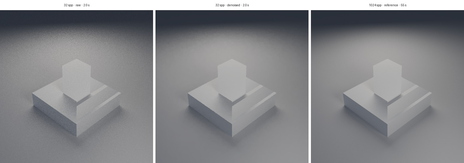
Honesty: the luminance edge-stopping weight is scaled by the estimator's own variance rather than a fixed sigma, because a fixed sigma makes a firefly self-protecting — its own noise spike makes every neighbour look like a different surface, so the filter rejects them all and the one pixel that most needs help survives untouched. Pixels whose primary ray escaped to the backdrop are passed through untouched, and no surface pixel accepts a tap from one: that is what keeps silhouettes exactly as sharp as the tracer drew them, and keeps an HDRI backdrop's own detail intact, but it also leaves backdrop noise from a wide aperture alone. The filter is spatial and single-frame — no temporal reprojection — so it cannot recover detail no sample ever found, and at very low sample counts a smooth indirect gradient is reconstructed rather than resolved. Pass --no-denoise whenever the noise itself is the measurement.
GPU Compute
vcad-kernel-gpu offloads mesh work — normal computation, decimation — to wgpu compute shaders.
Interoperability
-
STEP —
vcad-kernel-stepreads and writes STEP AP214, the lingua franca of mechanical CAD. Drag a.stepfile into the app and it becomes an editable BRep. -
URDF —
vcad-kernel-urdfimports robot descriptions (links, joints, inertials) as vcad assemblies ready for simulation. -
Feature recognition —
vcad-kernel-featuresreads a vendor STEP back into design intent: cylindrical faces become holes and bosses, equal-radius coaxial holes become bolt circles, and the report carries bolt-circle diameter, hole diameter, count, and each hole's angle relative to its pattern. Absolute angles depend on how the vendor happened to place the model, so the same part reads differently in two files; relative angles don't. Concentric patterns also get a clocking relation — the RobStride RS03's three output dowels come back as "bisects adjacent holes of the six-hole circle" rather than as three placement-dependent numbers. The envelope is measured from the largest coaxial cylinder, not the bounding box: an actuator with an asymmetric connector boss has a bbox far wider than its body, and the body OD is the number you need when cutting the bore for it.vcad features RS03.stp --min-count 3 # or --json for the full reportbody OD 100.500 mm (largest coaxial cylinder; bbox across the axis reads 106.000) [4] 8 x Ø4.200 holes on BCD 98.000, 45.0000 deg spacing angles rel. to pattern: 0.000, 45.000, 90.000, ... first hole at 202.500 deg absolute (placement-dependent) -
Drafting —
vcad-kernel-draftinggenerates shop-ready 2D drawings: orthographic projections with hidden-line removal, full and offset (stepped) section views with hatching and cutting-plane callouts, detail views with scale bubbles, dimensions, GD&T annotations, title block / revision table / BOM entities, and deterministic PDF + DXF sheet export with ANSI/ISO line weights.
Simulation and Analysis
Assemblies, Mates, and Interference
vcad-kernel-assembly makes a document's instance transforms the single source of truth for where every part is, and then checks that they add up. An instance is a named part reference plus a full pose — translation, Euler rotation, and an exploded-view offset — authored in loon as [instance-at name part x y z rx ry rz] or [instance-exploded … ex ey ez]. pose_document evaluates the geometry once and returns world-space meshes; PosedAssembly::exploded(factor) slides each part along its declared offset, so a viewer, a render and a build sheet read one set of numbers instead of each hard-coding their own.
Mates are checks, not constraints. Nothing here moves a part or solves a residual: a mate is an assertion about what the transforms are supposed to achieve, re-verified against the poses and reported with the measured value next to the asserted one. Three kinds ship: mate-coaxial (two parts' reference axes lie on one line — antiparallel counts, a flipped part is still coaxial), mate-planar-offset (a stated distance along an axis: the z-stack of a layered machine, written down once rather than re-derived from design-doc prose and STL extents), and mate-pattern-phase.
mate-pattern-phase is the one that earns the module. Two parts each carry an n-fold circular pattern about a shared axis; pattern features sit every 360/n degrees, so the check poses both reference directions and reduces their relative clocking modulo the pattern pitch. A dual-rotor axial-flux motor specified as "front rotor: flip, clock 60°" carries 10 poles per disc — a 36° pitch — and 60 mod 36 = 24, folding to a 12° pole misalignment (60° electrical). That shipped, and was caught only later by redoing the arithmetic by hand for the next revision, which clocks 180°: 180 mod 36 = 0, exact alignment. The arithmetic is invisible in prose, trivially wrong by hand, and one modular reduction for a checker that can see both poses. That is also why it is a checker and not a solver — nothing was under-constrained; the number was simply wrong.
check_interference sweeps the posed assembly: an AABB broad phase, then mesh_clearance's triangle-BVH branch-and-bound on the survivors, reporting each overlapping pair with an approximate depth and a witness point. The tolerance is part of the design, not a fudge: real models carry deliberate sub-tenth-millimetre overlaps so unions print without a hairline seam, so InterferenceOptions::tolerance_mm is the depth below which an overlap is modelling slop rather than a clash, and ignore_pairs excuses a press fit that is supposed to interfere.
Honesty: kinematic degrees of freedom are out of scope. A mate never moves anything and knows nothing about joints; articulation stays with Joint and solve_forward_kinematics, whose poses this crate consumes when a document has a joint graph. "Backdrive the train and check it still clears" wants a DOF model layered on top of these checks. Mates also do not yet mirror: mirror-group-* handles translation-only instances, so a posed instance passes through a mirrored group unchanged.
Physics
vcad-kernel-physics converts BRep assemblies into articulated rigid-body simulations (phyz): revolute, prismatic, cylindrical, ball, and fixed joints, with a gym-style reset() / step(action) / observe() interface for reinforcement learning — actions as torques, position targets, or velocity targets. The step includes ground contact: each part's convex collision geometry is tested against a configurable ground plane (height, Coulomb friction, restitution — on by default at z = 0) and resolved with a velocity-level projected Gauss-Seidel impulse solve over the coupled contact manifold, so dropped bodies land and rest and legged assemblies can push against a floor instead of falling through the world.
Differentiable Geometry
vcad-kernel-diff is a differentiable seam through the kernel: it computes exact parameter sensitivities (dx/dθ) of tessellations, mass-property gradients, differentiable fillet radii, and reverse-mode adjoints — so you can ask "how does mass change per millimeter of this parameter?" and optimize designs with L-BFGS, including gradients through physics rollouts with contact.
Topology Optimization
vcad-kernel-topopt runs SIMP topology optimization — voxel FEA finding the stiffest material layout for given loads and supports, extracted back to a mesh via surface nets.
Molecular Simulation
vcad-kernel-atoms extends the kernel below the continuum: atomic and molecular design with molecular dynamics, energy minimization, ML potentials, and inverse material design.
Photonics Inverse Design
vcad-kernel-photonics is a 2D FDTD electromagnetics solver (Yee grid, TM/TE, CPML absorbing boundaries, slab-eigenmode sources, spectral flux monitors) with a discrete adjoint: exact gradients of transmission with respect to every design cell's permittivity at the cost of one extra simulation, validated against finite differences to 5×10⁻⁷. Density-based topology optimization (cone filter, β-scheduled projection) inverse-designs devices end to end — the flagship example produces a 1×2 power splitter hitting 3.06/3.01 dB per arm against the 3.01 dB ideal, exports the exact simulated pixel geometry as fab-ready GDS via vcad-gdsii, and emits vcad.photonics-claims/1 predictions with full solver provenance plus a Holds/Violated/Unmeasured compare() for when the chip comes back. The validation ladder tests against the discretization's own closed forms: numerical dispersion to 5×10⁻⁸, the exact discrete Fresnel coefficient to 10⁻⁴, an energy invariant conserved to 10⁻¹¹, and a measured −95.6 dB CPML floor. Out of scope, stated on every output: it is 2D with one polarization per run (exact for the 2D problem, qualitative for real chips — no effective-index reduction of 3D stacks is performed for you), materials are linear, lossless, and non-dispersive (one ε per material, right at the design wavelength), and there is no fab-variation model — the tape-out pack expects absolute insertion loss to violate on a 3D chip and says so up front.
Electromagnetic Fields
vcad-kernel-em replaces formula-grade electromagnetics — Wheeler coil formulas, reluctance networks, first-order motor constants — with solved fields. Three linear-statics formulations share one symmetric finite-volume core (every problem is ∇·(c∇u) = −s, relaxed by SOR with scale-invariant stopping): axisymmetric magnetostatics on ψ = r·Aθ, planar magnetostatics on Az with magnets as bound-current sheets, and electrostatics on φ, with nonlinear B–H (damped Picard) and AC phasor eddy currents layered on top. Every output — inductance, capacitance, stored energy, force, torque — is computed by two independent routes (energy vs. flux linkage, Maxwell stress vs. J×B) and the gap between them ships on the claim as cross_route_residual. A discrete adjoint prices coil currents, magnet strength, and per-region μr in one extra solve on the same operator (FD-validated: current gradients to 10⁻⁵, μ gradients to ~10⁻³; gradients through saturable materials are refused rather than mispriced). The ladder runs from exact anchors (infinite solenoid converging O(h²) to 6×10⁻⁵, coax capacitance within 0.2%) through published results (finite-solenoid inductance within 0.15% of Wheeler's 1928 formula, coaxial-loop mutual inductance within 3% of Smythe, force cross-checks to 0.08%) to a Jackson magnetic-shielding problem whose staircase error is stated at every resolution — 32.7% at h = 1 mm down to 1.7% at h = 0.25 mm, and at h = 2 mm the answer is garbage, which is part of the result. Emits vcad.em-claims/1 predictions with a fail-closed Holds/Violated/Unmeasured compare(); the measurement pack binds a bench motor build to those claims (predicted 4.64 mN·m at 1.5 A, with a 1.6% cross-route residual). Out of scope: 3D, hysteresis, saturation combined with AC (harmonic balance), and FEM-grade curved boundaries — material edges staircase at grid resolution, an O(h) bias the ladder measures rather than hides.
Antenna Analysis
vcad-kernel-antenna predicts input impedance Zin(f), S11, resonance, and far-field gain, directivity, and radiated power for wire antennas — dipoles, monopoles over ground, loops, folded dipoles, Yagis, top-hat verticals — from wire lists or ECAD traces (a flat strip maps to a round wire of radius w/4). The method is the thin-wire mixed-potential EFIE: triangular current bases with Galerkin testing, singularity-extracted quadrature, a delta-gap feed, and a hand-rolled complex dense LU with zero external dependencies. Validation runs from Balanis closed forms (half-wave dipole resonance at ℓ/λ = 0.479 with R = 71.9 Ω against the ideal 73 + j42.5, broadside directivity 2.138 dBi vs. the published 2.15) through NEC-2 reference cases (within 3.7–4% of NEC's impedances) to physics invariants (reciprocity to 10⁻⁹, radiated-over-input power within 3%). Geometry outside the thin-wire regime fails closed — segment-to-radius and electrical-size gates are hard errors, never silent degradation, and NEC's own thick-loop example is refused rather than answered badly. An adjoint identity prices dZin/dp for spec parameters in one solve (FD-validated to 10⁻⁴; a Newton step retunes a 10%-detuned dipole to resonance in ≤5 steps). Emits vcad.antenna-claims/1 predictions with fail-closed Holds/Violated/Unmeasured compare(), and the measurement pack closes the loop for about $100: sweep a 915 MHz PCB monopole with a NanoVNA, save the Touchstone .s1p, and grade the claims. Honesty: no dielectric substrates yet — FR-4 pulls resonance down roughly 30–40% for microstrip-like traces, so until the substrate model lands, PCB predictions are trends, not numbers; conductors are PEC (radiation efficiency ≡ 1); no patches, apertures, or full-wave 3D.
Charged-Particle Optics
vcad-kernel-particle simulates charged-particle optics in axisymmetric electrode devices — fusors, magnetically shielded-grid IEC machines, ion sources — as vacuum-field single-particle physics: electrode geometry → fields → trajectories → figures of merit. Fields come from an axisymmetric Poisson solve (SOR) plus exact ring-coil B via complete elliptic integrals; a Boris pusher with adaptive substepping traces ions to wire, wall, or survival; Bosch–Hale D-D cross sections (both branches) weight each trajectory into neutron yield, with an optional charge-exchange survival model. A discrete adjoint back-propagates ensemble yield through the whole chain — reverse Boris, deposits into the potential grid, one adjoint Poisson solve — pricing every ring potential, the wall potential, and every coil's ampere-turns (FD-validated to 0.1–0.8%). The ladder anchors elliptic integrals to Abramowitz & Stegun at 10⁻¹², Bosch–Hale to published cross-section anchors, and mirror loss cones and axial oscillation periods to analytic estimates — then reproduces the magnetically shielded-grid effect from arXiv:1510.01788 (interception falls, core passes rise) and the rL ∝ √V scaling that lets low-voltage shielding data transfer to fusion voltages. Claims ride the unified receipt's open domain vocabulary: vcad.particle-claims/1 (interception, transparency, D-D neutron rate, Q, distance-to-Lawson) with basis predicted, so a receipt rolls up Provisional, never Pass, until measured — the flagship fusor card reads Q = 4.1×10⁻¹⁰, 9.4 orders of magnitude from breakeven, stated exactly. The MCP tools simulate_charged_particles and optimize_electrodes (multi-start search over electrode specs) put the loop in agents' hands. Honesty: no space charge, no plasma physics — single-species vacuum optics in the regime where geometry dominates; predicted neutron rates are floors; and it does not claim a path to net energy gain.
Neutron Transport
vcad-kernel-neutronics is an analog Monte Carlo neutron-transport solver for benign shielding design: a layered shield (slab stacks or concentric spherical shells) around a 2.45 MeV D-D source goes in; per-region flux, leakage, thermalization observables, and ambient dose equivalent H*(10) come out — every tally a mean with its relative standard error, and a zero-scored tally reports infinite error rather than silence. The physics is five energy groups with exact two-body elastic kinematics (correlated outgoing energy and lab angle), absorption, and downscatter, with per-batch conservation asserted to 10⁻¹²; dose conversion is anchored to ICRP-74. A deterministic adjoint-diffusion companion prices d(dose)/d(layer thickness) in one extra solve — FD-validated against the Monte Carlo itself to ~25%, with its ~1.5× absolute bias vs. MC measured and stated rather than hidden. Validation: uncollided flux against e^(−Σr)/4πr² within 4σ, slab transmission at 3 mean free paths against the exact 0.049787, 1/√N error scaling asserted, and textbook thermal benchmarks quoted with their misses — water diffusion length −25%, Fermi age +23% — inside bands stated exactly that wide. Emits vcad.neutronics-claims/1 (dose rate, attenuation factor, thermal flux; basis predicted) with a fail-closed Holds/Violated/Unmeasured compare() whose bands widen by both measurement and Monte Carlo σ. The honesty section is load-bearing: fission is refused permanently — no fission cross sections, no keff, not at any milestone; the cross-section library is a named design-estimate set good to ±20–30%, not evaluated nuclear data; capture gammas are not transported (budget them separately); and results are free-field — real rooms scatter neutrons back, and that return is unmodeled.
Lattice Gauge Theory
vcad-kernel-qcd computes confinement from first principles: quenched pure-gauge Wilson-action Monte Carlo on a 4D periodic lattice, laptop-scale, in both SU(2) (quaternion links, exact Kennedy–Pendleton heatbath) and SU(3) (3×3 complex links, Cabibbo–Marinari subgroup updates, det = +1 Gram–Schmidt reunitarization) — one generic lattice over a GaugeGroup trait, bit-reproducible per seed. Observables leave the crate only as binned-jackknife estimates (a mean without an error bar is unrepresentable): plaquette, planar and spatial×temporal Wilson loops (optionally APE-smeared), Creutz ratios and the effective static potential with a Cornell-form fit (the string tension σa²), the Polyakov-loop magnitude ⟨|L|⟩ (deconfinement order parameter), and per-configuration field exports for the viewport — action density, complex Polyakov field, cooling sweeps, naive clover topological charge (near-integer after cooling), and the static-pair flux-tube profile behind the drag-the-quarks demo. CI oracles: SU(2) strong/weak coupling expansions (β/4 − β³/96; 1 − 3/(4β)), SU(3) expansions (β/18; 1 − 2/β), the exact strong-coupling string tension σa² = −ln(β/4) recovered by both χ(2,2) and V(1), Polyakov-pair correlator decay with separation in the confined phase, and the deconfinement transition bracketed in both groups at N_t = 2. Emits vcad.qcd-claims/1, fail-closed: statistics-starved runs mint nothing; every logarithm requires its loops ≥ 3σ from zero. Honesty bounds travel with every claim: quenched, lattice units at fixed coupling — no continuum limit, so nothing here is a number about physical QCD, and the claims say so. The ladder is docs/qcd-m0.md (M0–M3 complete); dynamical QCD at physical parameters is permanently out of scope.
Thermal Analysis
vcad-kernel-thermal solves steady and transient heat conduction on a voxel grid: materials, power sources, and fixed-temperature reservoirs are painted as box and cylinder regions (or supplied per-voxel), domain faces take Dirichlet, convection-film, or adiabatic conditions, and a harmonic-mean finite-volume operator is solved matrix-free with Jacobi-preconditioned conjugate gradients (backward Euler in time). Outputs: the temperature field, Tmax and its location, per-source thermal resistance θ, per-reservoir heat flows — and an energy-balance residual reported on every solve (typically ~10⁻¹¹). Because the conduction operator is self-adjoint, the exact gradient of a smooth-max hot-spot objective with respect to every conductivity, film coefficient, and source power costs one extra CG solve (FD-validated: source powers to 2×10⁻⁹, conductivities to ~10⁻⁶). The ladder is analytic end to end: composite slabs exact to 2.8×10⁻¹⁴ °C at a 200:1 conductivity contrast, Robin films exact from h = 50 to 10⁹, cylinder shells converging under 5%, transient lumped-capacitance and semi-infinite erfc solutions within 0.5% and 1.5%. Emits vcad.thermal-claims/1 (Tmax, θJA, energy balance; basis predicted) with fail-closed Holds/Violated/Unmeasured compare() — and it refuses floating regions, sources painted into empty space, and non-converged solves rather than returning plausible numbers. Honesty: pure conduction — no radiation, no fluid flow; convection enters only as a supplied film coefficient, and that h is the biggest uncertainty in every prediction (natural-convection correlations carry ±20–30%). Its own M1 study measured the "isotropic board" idealization under-reading a chip's θJA by 43% — don't adjective an error you can compute.
Structural FEA
vcad-kernel-fea answers the everyday question — will this bracket break? — on the part's real geometry: the tessellated boundary is filled with a lattice of linear tetrahedra (Kuhn decomposition, face-conforming and watertight by construction), and a constant-strain-tet linear-elastic solve (matrix-free Jacobi-PCG, mm-N-MPa units) returns max von Mises stress and its location, max displacement, compliance, and — given a yield strength — a safety factor. The load-bearing feature is the fail-closed mesh-convergence gate: every analysis solves at two or more refinement levels, the inter-level change of each QoI is reported as its discretization-error estimate, and a study whose QoIs disagree beyond stated tolerances is Unverifiable — no safety factor, no claims, with the reason spelled out (including "your peak stress sits on a singular re-entrant corner; fillet it", which is design feedback, not solver failure). Validation is closed-form: axial bar compliance within 3% of FL/(EA), a cantilever converging monotonically from below onto the Timoshenko deflection, exact 1/E displacement scaling, exact volume recovery on lattice-aligned geometry. Converged studies emit vcad.fea-claims/1 (stress, displacement, safety factor, plus the discretization-error conscience claims; basis predicted — receipts roll up Provisional until the part is load-tested); unconverged ones poison the receipt with a single unverifiable claim so nothing quietly passes. Honesty: small-displacement linear elasticity of one isotropic material — no plasticity, buckling, contact, or dynamic loads; the boundary is staircase-approximated at the lattice pitch (priced by the gate); constant-strain tets smear stress concentrations, so the reported peak is a lower bound that tightens with refinement. Exposed over MCP as analyze_structure; predict_physics remains the fast voxel-hex steering loop.
Thin walls take the other route. A staircase lattice needs several cells through the thinnest load-bearing section, and sheet metal does not offer that at any affordable pitch: a 2 mm wall on a 312 mm member wants a 0.33 mm pitch, about 950 cells along the longest axis. So analyze_structure measures the part first (axis-aligned solid-span sampling, 5th percentile as the working thickness) and, below ~4 cells through the section, refuses with the arithmetic spelled out — pitch, cells through the wall, the resolution six cells would need, whether that is even reachable — and names where to go instead. That matters because the refusal is right but a refusal without a route forward costs an afternoon. Above the wall it also forces Unverifiable when the QoIs happen to agree: a study that never resolved the wall can agree with itself and still be describing a different part.
beam_check is that route, and for a prismatic member it is not a fallback but the more accurate answer. Give it a profile (rect, rect tube, round, round tube, I-section), a span, an end condition and a load case; get exact section properties (A, I, section moduli, J, torsional stiffness), stresses, deflection with the Timoshenko shear term, twist, the Euler buckling load, and a safety factor. Torsion carries its provenance rather than a table lookup: exact for round sections at any wall, the convergent Saint-Venant Fourier series for solid rectangles (reproducing the classical J = 0.1406 s⁴ and τ = T/(0.208 s³) square-bar constants), Bredt closed thin-wall theory for rectangular tube, and the thin-strip sum for the open I-section, which says outright that it ignores warping. It gates its own applicability the same fail-closed way — too stubby for beam theory (L/depth < 5), a wall too thick for Bredt, deflection past a tenth of the span, torque on an open section, or an Euler margin under 1 → Unverifiable, nothing claimed, each reason naming the route forward (usually back to analyze_structure, since a stubby part is exactly what a lattice can resolve). Validated against the same aluminum cantilever the lattice is (0.301 mm Timoshenko tip deflection to within 2%), the classical torsion constants, and hand-computed Bredt values. Claims ride the same vcad.fea-claims/1 schema under structure.beam.* with basis predicted. It needs no document — geometry by description, so it works before the part exists. What neither route covers: a non-prismatic thin-walled part (a bent bracket with cutouts) still has no audited answer; shell and beam elements are the real fix.
Tolerance Stackup
vcad-kernel-tolerance prices dimensional tolerance stacks: will this assembly fit, and at what yield? A stack of contributors (nominal, signed coefficient, drawing limits, deviation distribution) plus a requirement produces the worst-case interval, exact RSS moments and yield, a seeded Monte Carlo fit probability (xoshiro256++ — bit-reproducible, no rand dependency), Cp/Cpk, and ranked sensitivities. Sensitivities are closed-form, not finite differences: variance shares that sum to one and per-contributor yield derivatives (validated against FD to 10⁻⁴). Beyond linear chains it gauges GD&T bolt-circle fits directly — reporting the virtual-condition worst case alongside the true Monte Carlo fit rate (a stack the VC check fails outright can still fit 87% of the time, and both numbers are stated) — allocates tolerances at minimum cost against a yield target, and binds measured coupon scatter back onto the assumed distributions. Validation is exact where exactness exists: hand-computed textbook chains asserted to 10⁻¹², yield against the normal table to 10⁻⁶, RSS ≡ Monte Carlo within four standard errors, Irwin–Hall closed forms bounding the CLT error, 1/√N convergence asserted. Emits vcad.tolerance-claims/1 (fit probability, RSS yield, Cp/Cpk, worst-case margin; basis predicted) with fail-closed Holds/Violated/Unmeasured compare(). Honesty: the ±tol↔σ convention buries more products than any solver bug, so the default (±tol = 3σ) ships as recorded provenance, never silently; contributors are assumed independent — two dimensions cut in one fixture make RSS and Monte Carlo both wrong about their sum; linearized radial projections are measurably optimistic (~1.9 points at c/σ = 2.7); and there is no full 3D tolerance-zone simulation or datum-reference-frame gauging (the 3DCS/CETOL feature set).
Structural Strike (bar modal synthesis)
vcad-kernel-acoustics::strike is the structure-side half of the acoustics loop: a mallet strike on a flat free-free bar (glockenspiel / vibraphone bar), from geometry to a pitch verdict you can hear. Modal frequencies come from both the closed-form Euler–Bernoulli model (fₙ = (βₙL)²/(2πL²)·√(EI/ρA), cosh βL · cos βL = 1, Newton-refined roots) and a hole-aware 1-D Hermite-beam FEM — the cord suspension holes enter as the exact material width w_eff(x) = w − 2√(r²−(x−x₀)²) feeding A(x) and I(x) at each Gauss point, solved as a dense generalized symmetric eigenproblem (Cholesky congruence + cyclic Jacobi, ~200 DOF). Strike physics: modal gains are the mode shape at the strike point filtered by a half-sine mallet contact spectrum; decay is Q-based (material Q + a suspension heuristic ∝ φₙ² at the holes — the audible reason the holes sit on mode 1's nodal lines). The verdict is a real round trip: synthesize decaying sinusoids → 16-bit WAV → Hann-windowed FFT → parabolic peak interpolation → cents vs the target note. Pinned tests reproduce the exact βL roots, FEM-vs-closed-form agreement below half a cent on a uniform bar, the non-harmonic 2.7565/5.4039 overtone ratios, and a synth→FFT round trip inside one cent — the physics the glockenspiel build verified with a microphone to −5 cents. Exposed over MCP as simulate_strike (the server only marshals; all numerics run in this crate via WASM). Honesty: 1-D transverse bending only (no torsional or lateral modes), and decay Q is a heuristic while the frequencies are not.
Air Acoustics
vcad-kernel-acoustics is the air-side complement to structural acoustics (the simulate_strike bar solver above models how a solid vibrates; this models how the air resonates and radiates). It solves the driven Helmholtz field (∇²+k²)p = −jωρ·s for cavities, ports and boxes on an axisymmetric (r, z) grid with a vertex-centred finite-volume discretisation: conservative, symmetric — so field reciprocity (source ↔ receiver) holds to round-off (measured 4.5×10⁻¹⁶) — and exact on the axis via r-weighted control volumes. The operator is indefinite (singular at every resonance), so it is solved directly by block-Thomas, never relaxation. Resonances are read the way a bench does it: sweep a driven source, peak-pick |p| — no eigen-decomposition. The lumped spine (duct acoustic mass, cavity compliance, Helmholtz/bass-reflex tuning f_b = (c/2π)√(S/(V·L_eff)) with Beranek/Kinsler end corrections) is both a feature and the field solver's oracle, and a baffled-piston radiation model (Rayleigh integral + on-axis closed form + J₁ directivity) covers the open-domain side analytically. The ladder is closed-form: rigid closed-cylinder axial modes fₙ = n·c/2L reproduced to 0.04–0.1%, second-order grid convergence to a named 0.005% floor (19× error drop over 4× refinement), the numeric Rayleigh integrator recovering the analytic on-axis pressure and the piston directivity null at ka·sinθ = 3.8317. The flagship examples/ported_box.rs prices a bass-reflex enclosure's port tuning, confirms it against the field sweep, then lets the optimizer size the port length for a target tuning (120 → 339 mm, retuning 72 → 45 Hz against the field solve itself). Emits vcad.acoustics-claims/1 (tuning, mode frequencies, response at listed points; basis predicted — receipts roll up Provisional, never Pass), with a compare() that names a calibrated measurement microphone + swept sine as the closing instruments — the same loop the glockenspiel closed to −5 cents. Honesty: linear, lossless acoustics — no thermoviscous or radiation damping, so resonator/port Q reads optimistic and every claim says so; the pressure-release mouth omits the exterior radiation mass, so field tuning reads ~15% high of the fully end-corrected lumped value (a radiation-impedance mouth is M1); structural↔air coupling (a vibrating cone/bar radiating into a modelled room) is M2 — M0 states the surface-velocity-in, pressure-out seam and keeps the two solvers independent.
Fluid Flow
vcad-kernel-flow answers the pipe-and-duct questions — what pressure drop does this manifold cost, how much heat does this cold plate pick up? — with a steady laminar D3Q19 BGK lattice-Boltzmann solve on a voxel grid: regions painted as boxes and tubes (solid, fluid, velocity inlet, pressure outlet), half-way bounce-back walls, moving-wall inlets, anti-bounce-back outlets, optional body-force drive with periodic boundaries, and an advected temperature field with isothermal walls and Boussinesq buoyancy. It is a deliberate two-route design: every field solve is paired with lumped oracles (Poiseuille pipe, rectangular-duct friction, Darcy–Weisbach, Borda–Carnot, entrance length) so a cross_route_residual can price the disagreement between the lattice and the textbook whenever the geometry admits one. Steadiness is detected, not assumed — the velocity field's relative L∞ change per check interval must fall below tolerance, and a run that never gets there is an error, not a result — and every solve reports a mass-balance audit (|Q_in − Q_out| normalized) that closes to solver tolerance or the answer is wrong. The validation ladder: Poiseuille channel and pipe profiles under 1% of the parabola, the Shah–London rectangular-duct constant f·Re = 56.91 recovered, the Ghia et al. Re = 100 lid-driven cavity centerline benchmark, the de Vahl Davis Ra = 10³ natural-convection cavity at Nu = 1.118, and a heated-duct energy audit closing wall heat against fluid enthalpy pickup within 5%. Emits vcad.flow-claims/1 (pressure drop, flow rate, max speed, mass audit, outlet temperature, heat pickup; basis predicted — receipts roll up Provisional, never Pass until a manometer and a flow meter close the loop). Exposed over MCP as simulate_flow (summary + claims by default; the grid-sized per-voxel fields only behind include_fields). Honesty: laminar only — fail-closed gates refuse Re > 2300, a BGK τ outside the validated stability window, and Ra > 10⁸, rather than returning turbulent-regime fiction; the scheme is weakly compressible, so pressure carries O(Ma²) noise (stated on every claim); walls are voxel staircases at the grid pitch, which taxes friction on any surface not axis-aligned; and conjugate heat transfer is a film-averaged seam to solve_thermal, not a monolithic solve.
Manufacturing
- CAM —
vcad-kernel-camgenerates 2.5D machining toolpaths with a G-code post-processor. - Stock simulation —
vcad-kernel-stocksimverifies toolpaths against an octree-SDF stock model, acting as a fail-closed oracle for CAM output. - DFM —
vcad-kernel-dfmchecks designs against manufacturability rule packs (minimum wall thickness, drill standards, etc.) and suggests fixes. - Cost —
vcad-kernel-costestimates manufacturing cost with a shared model used by quoting tools.
One Kernel, Every Surface
Everything above compiles to a single unified API in vcad-kernel, which is consumed three ways: natively by the CLI and MCP server, via vcad-kernel-wasm in the browser (the same kernel runs client-side at vcad.io), and through the IR format that makes every model a reproducible, parametric program.
Every figure on this page was generated headlessly: loon source evaluated by vcad-loon, rendered with cargo run -p vcad-render -- part.vcad --jpeg out.jpg. No screenshots, no external renderer — the kernel drew its own documentation.